Little Bird to Police Chopper Custom Update 8-23-09
Posted: Sat Mar 07, 2009 11:42 pm
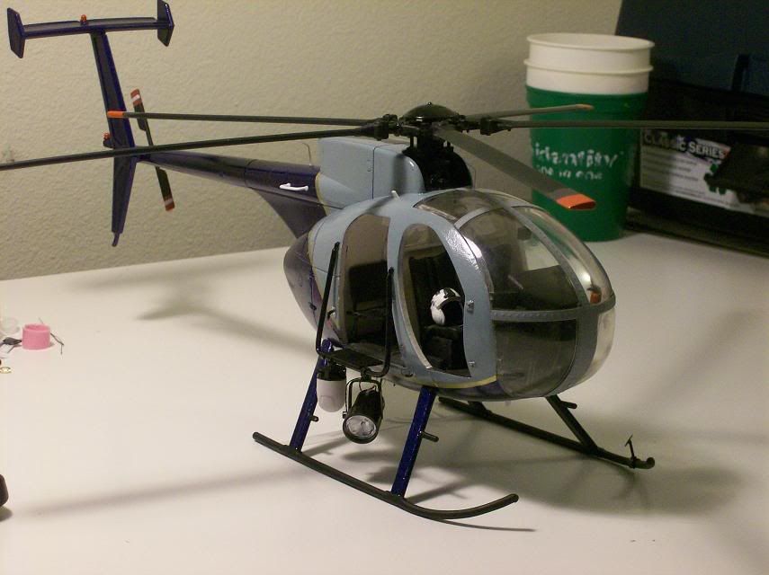
A long time ago I bought a BBI Little Bird from TRU. I was on the fence about getting one for a while because I thought it wasn't quite as good as it could have been, but it was the only game in town---so I bought it, and it hung on the wall for years.
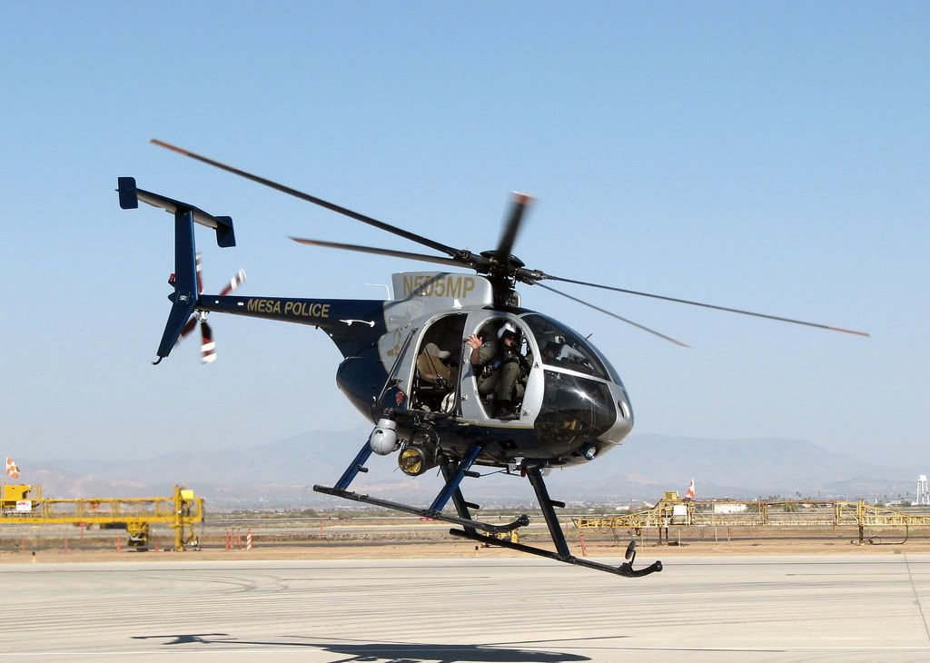
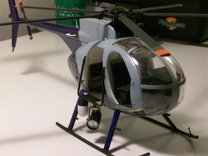
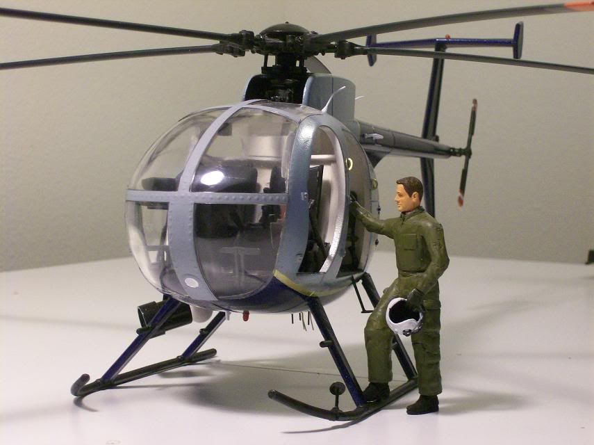
Now, boys and girls, I can build the heck out of a model kit, but I had never tried customizing any of my 1/18 stuff, even though I had toyed with the idea more than once. But a couple of weeks ago I ran across a cool picture of a 500 series helicopter in use by the Mesa, AZ police dept. The Mesa chopper is an E model with the pointed nose, but after poking around the internet I was able to find lots of police 500's, even a few D models like the Little Bird. I looked up at the Little Bird on the wall, and came up with the beginnings of a plan...
Maybe some of you have heard of Plastruct, retailers of all things scratch-build. Gods bless 'em. My first step in my evil plan was to buy thirty bucks worth of assorted styrene stock from them. rods, tubes, sheets, and angle beams. So armed with a tube of Loc-tite cyanoacrylate, a hobby saw, a knife, and some sandpaper, I went to work.
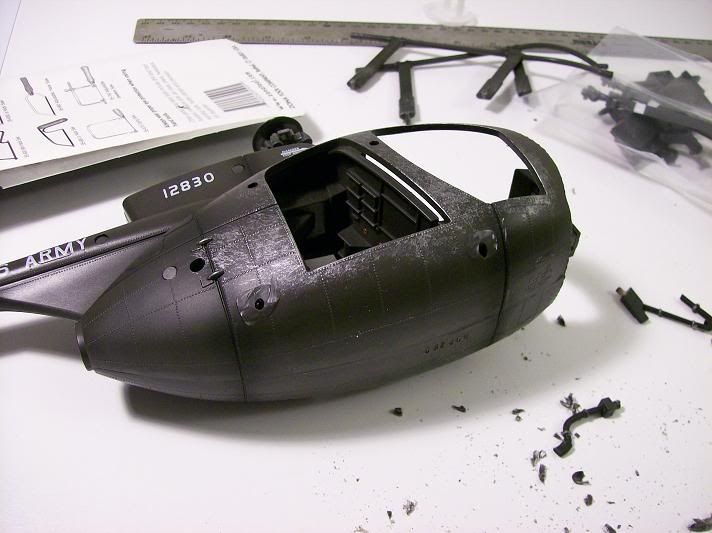
Disassembling a Little Bird was interesting, but I managed it without destroying anything I needed to reuse. The canopy glass is glued and screwed on, and the scew is almost impossible to reach beneath the floor without splitting the body in two. I managed. Most of the pieces came apart with a minimum of profanity from me.
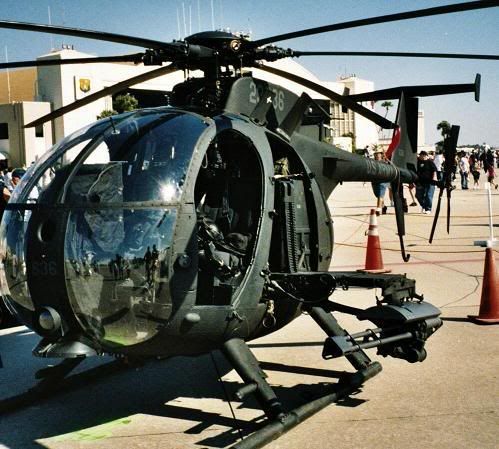
The more research I did on Hughes/McDonnell Douglas MD500D helicopters, the more I realized how much would have to be done to the Little Bird. My wife calls this level of detail fixation "geeking out". I assured her it could be worse. BBI got the basic shape right, but let's leave it at that.
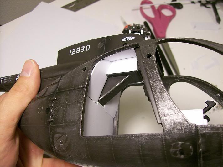
The skid mounts were the first things I went after. The BBI bird has bulging mounts which i had to shave off, which in turn will require some work to the skids themselves.
Next, the rotor mast is too high. The cap is also too far above the blades and the swashplate assm. is too wide. I took the whole thing apart, and without getting too "geeky" I rebuilt and cut down the necessary parts. (The metal shaft that everything rides on had a bit of play in it up and down. I hadn't pulled it all the way up in the second pic.)
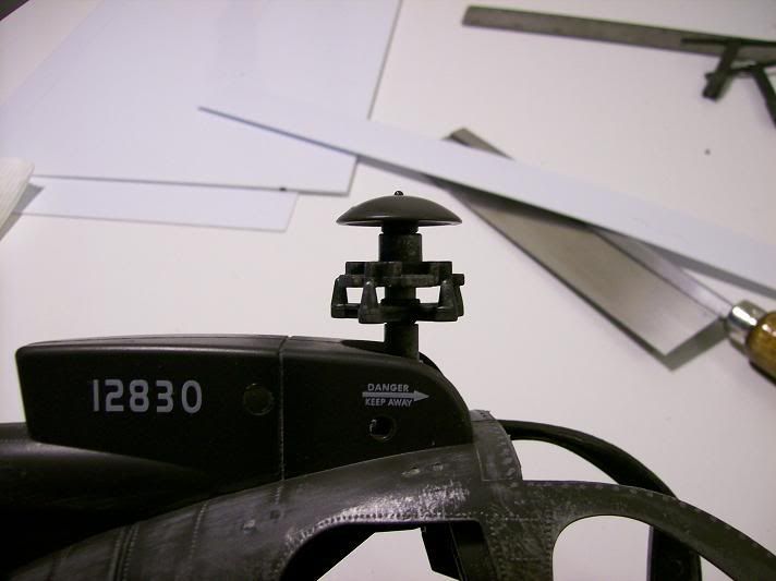
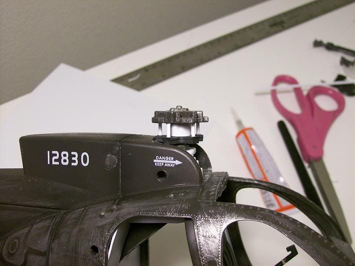
The swashplate assm. is supposed to fit a little inside the rotor fairing. As it was, the stock assm. wouldn't even come close, being too wide, which might be why BBI made the whole rotor assm. too tall in the first place. Actually, most of the rotor parts are a little too big. I cut down the swashplate and built new linkages, cut down the height of the rotor base, and cut down the base of the rotor cap so it sits closer to the rotor hub (not shown in pic). It ain't perfect, but it'll do. The blades themselves may need some work on the bits attaching to the hub too, but I'll deal with that later.
RANDOM NOTE:
Those of you with firsthand experience with 500 series aircraft are politely asked to go easy on me (Tambo, I'm talking to you).
Next, the cockpit. Oh boy was this off. Bad. Everything had to come out. The seats are on the floor, which is wrong. the cyclics are mounted on some sort of island in the middle of the floor---wrong. The instrument panel is a flat piece of plastic with gauges and a hood. The foot petals were flat pieces of plastic and the collectives were WAY to long. The right side collective was also mounted too high. So I started ripping it all out. I had to cut the weird little island out of the floor. The front glass had this big attachment points that fit pegs halfway up the inside of the front cabin frames. I cut and sanded all of that off---they were a bit too obvious. I think the glass will glue on just fine without them.
Next I replaced the floor for obvious reasons with thin styrene sheet and made foot pads for the petals.
I figured I could reuse the instrument panel, because scratch-building the whole thing scared me. I used styrene sheet again to build it.
Now boys and girls, 500 series helicopters have been produced since the sixties, with a ridiculous number of models, configurations, and options, but I don't think there was ever an instrument pedestal produced that looked just like mine. At this point I'll make the disclaimer that all of the stuff I'm doing to this helicopter will be CLOSE to reality, but definitely not EXACT. Maybe I could, but I don't think my patience would allow me to.
Next was the foot pedals.
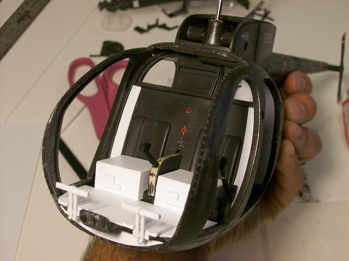
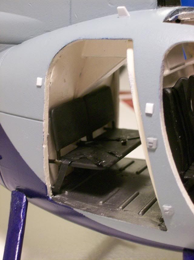
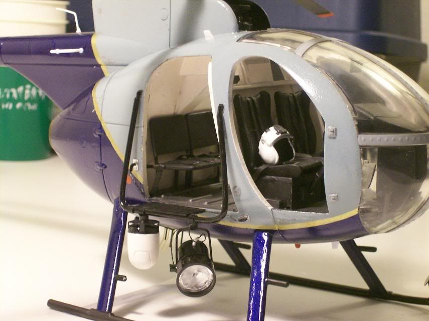
In the pic you can also see I built the seat bases and closed up an annoying gap between the front bulkhead and the frame on both sides. There are a lot gaps in this thing, actually. I had to clamp and glue the front floor down before adding the styrene because it was flexed upwards so much. In the pic you can also see I cut the two openings in the bulkhead behind the crew's heads. This was lots of fun and I only cut myself twice. The little "L" shaped bits on the front of the seat bases are where the cyclics are actually supposed to be mounted.
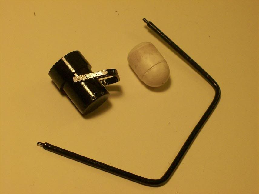
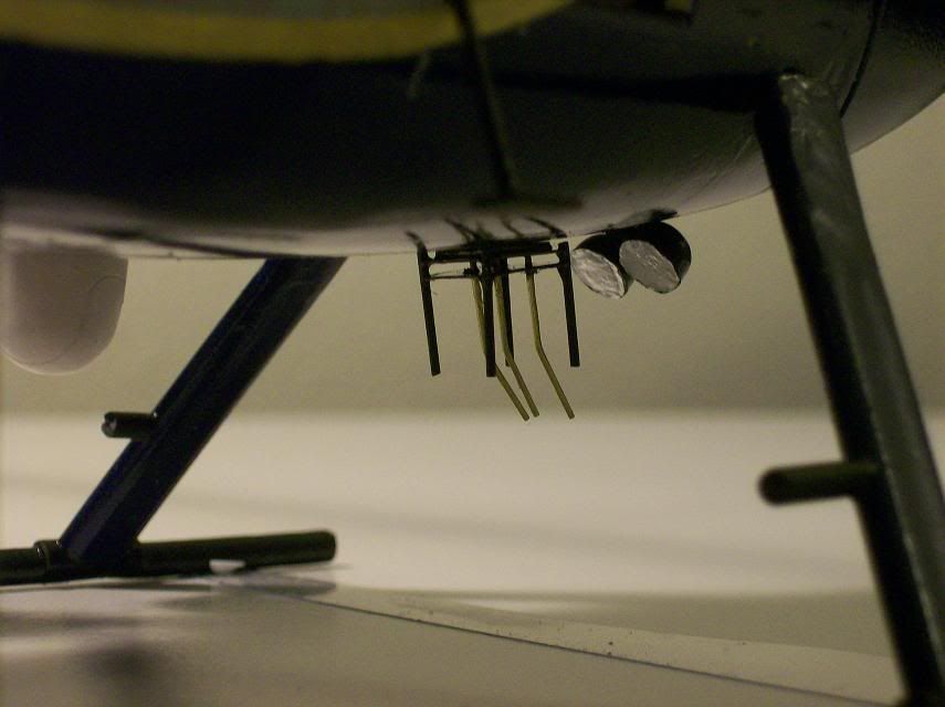
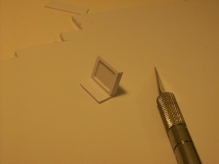
Most police helicopters nowadays are equipped with all sorts of electronic goodies, including a monitor and keyboard for the right hand seat. So, I needed a monitor and keyboard:
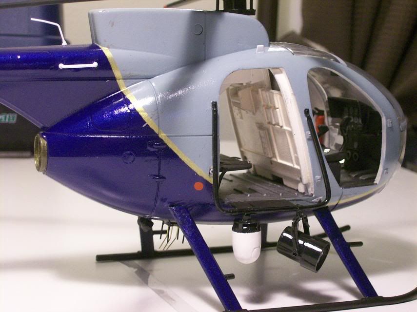
I mounted the pedestal and ran a piece of styrene tubing from there to the wall, and mounted the monitor on that. There are a bunch of different mounting methods I've seen on real helicopters, but this one was the easiest.
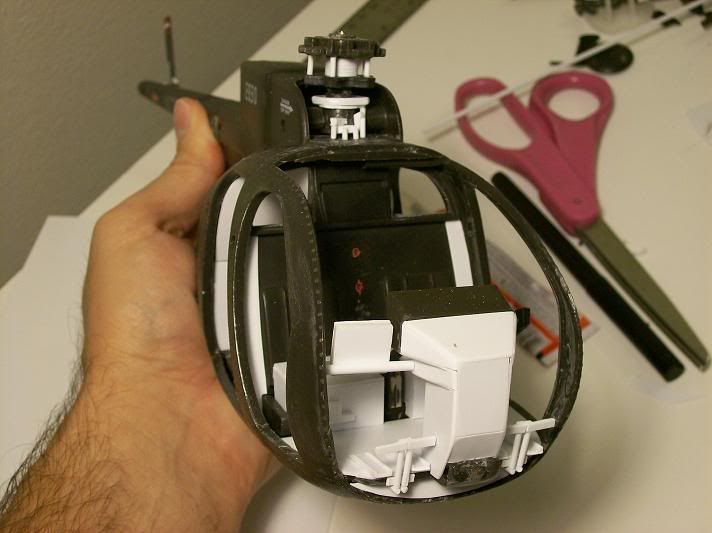
In the first pic you can see the modified rotor assm. again. I added a bit of the linkages that protrude upwards in front of the assm. It ain't all that accurate, but reproducing the real thing would have taken me about a month. I will later add a cable cutter right in front of the rotor assm.
The rear of the cockpit got some attention too. Gaps everywhere. The only thing I could do was close it all in with styrene sheet.
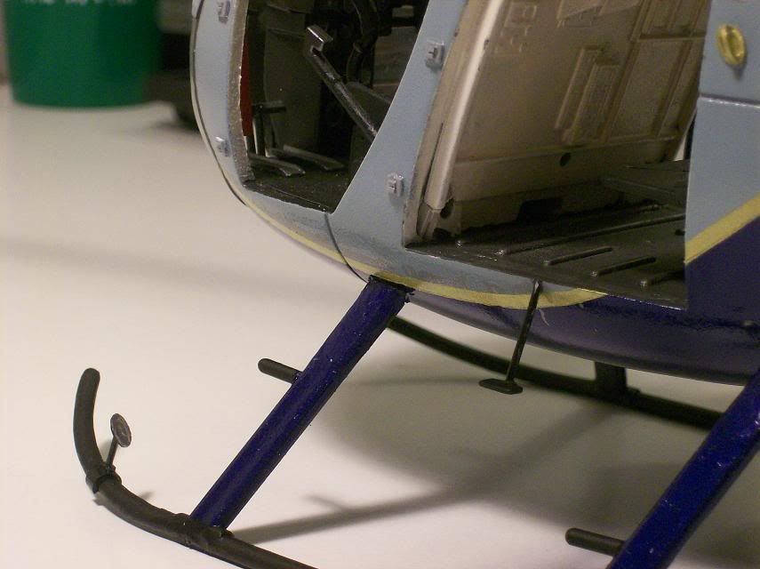
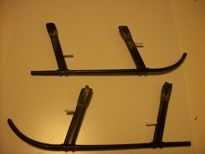
Next, the skids. Like I mentioned earlier, the mounting points needed to be adjusted because the body mounting points were cut down. Luckily, this involved removing material and not adding it. Always easier to remove. The fairings at the top of the skid legs were a bit too bulky and were cut down, as well as the bottom attachment points where skid and leg meet, although I hadn't yet done it all when I took the picture.
I also added the foot pegs with styrene rod.
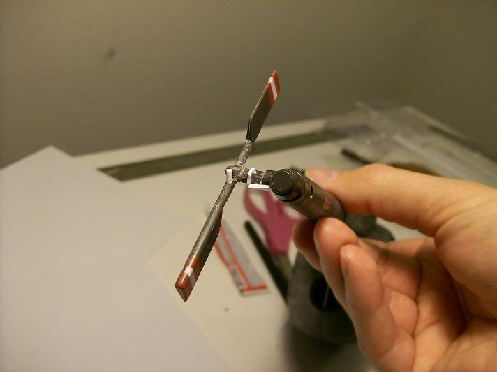
Tail rotor next. Way too bulky and simplified. I shaved some bits down and added the largest and most obvious parts of the linkage. I thought about adding a twin cascading rotor assm. but decided against it. I'll likely do more work to this part but I'll need some smaller styrene rod.
That's all I got for now. I'll likely do the seats next, so stay tuned!
Jeffrey
Now, boys and girls, I can build the heck out of a model kit, but I had never tried customizing any of my 1/18 stuff, even though I had toyed with the idea more than once. But a couple of weeks ago I ran across a cool picture of a 500 series helicopter in use by the Mesa, AZ police dept. The Mesa chopper is an E model with the pointed nose, but after poking around the internet I was able to find lots of police 500's, even a few D models like the Little Bird. I looked up at the Little Bird on the wall, and came up with the beginnings of a plan...
Maybe some of you have heard of Plastruct, retailers of all things scratch-build. Gods bless 'em. My first step in my evil plan was to buy thirty bucks worth of assorted styrene stock from them. rods, tubes, sheets, and angle beams. So armed with a tube of Loc-tite cyanoacrylate, a hobby saw, a knife, and some sandpaper, I went to work.
Disassembling a Little Bird was interesting, but I managed it without destroying anything I needed to reuse. The canopy glass is glued and screwed on, and the scew is almost impossible to reach beneath the floor without splitting the body in two. I managed. Most of the pieces came apart with a minimum of profanity from me.
The more research I did on Hughes/McDonnell Douglas MD500D helicopters, the more I realized how much would have to be done to the Little Bird. My wife calls this level of detail fixation "geeking out". I assured her it could be worse. BBI got the basic shape right, but let's leave it at that.
The skid mounts were the first things I went after. The BBI bird has bulging mounts which i had to shave off, which in turn will require some work to the skids themselves.
Next, the rotor mast is too high. The cap is also too far above the blades and the swashplate assm. is too wide. I took the whole thing apart, and without getting too "geeky" I rebuilt and cut down the necessary parts. (The metal shaft that everything rides on had a bit of play in it up and down. I hadn't pulled it all the way up in the second pic.)
The swashplate assm. is supposed to fit a little inside the rotor fairing. As it was, the stock assm. wouldn't even come close, being too wide, which might be why BBI made the whole rotor assm. too tall in the first place. Actually, most of the rotor parts are a little too big. I cut down the swashplate and built new linkages, cut down the height of the rotor base, and cut down the base of the rotor cap so it sits closer to the rotor hub (not shown in pic). It ain't perfect, but it'll do. The blades themselves may need some work on the bits attaching to the hub too, but I'll deal with that later.
RANDOM NOTE:
Those of you with firsthand experience with 500 series aircraft are politely asked to go easy on me (Tambo, I'm talking to you).
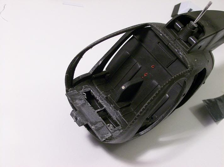
Next, the cockpit. Oh boy was this off. Bad. Everything had to come out. The seats are on the floor, which is wrong. the cyclics are mounted on some sort of island in the middle of the floor---wrong. The instrument panel is a flat piece of plastic with gauges and a hood. The foot petals were flat pieces of plastic and the collectives were WAY to long. The right side collective was also mounted too high. So I started ripping it all out. I had to cut the weird little island out of the floor. The front glass had this big attachment points that fit pegs halfway up the inside of the front cabin frames. I cut and sanded all of that off---they were a bit too obvious. I think the glass will glue on just fine without them.
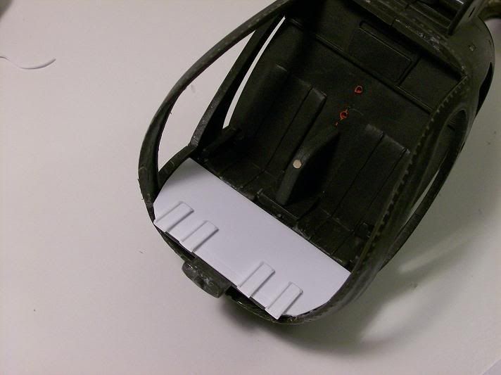
Next I replaced the floor for obvious reasons with thin styrene sheet and made foot pads for the petals.
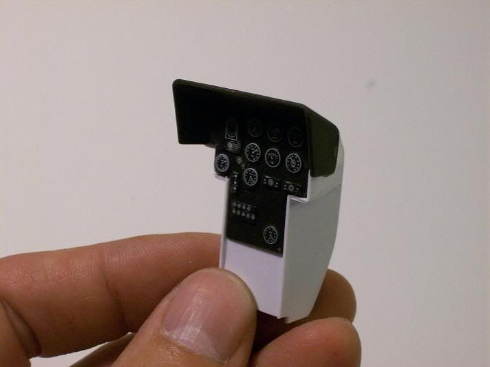
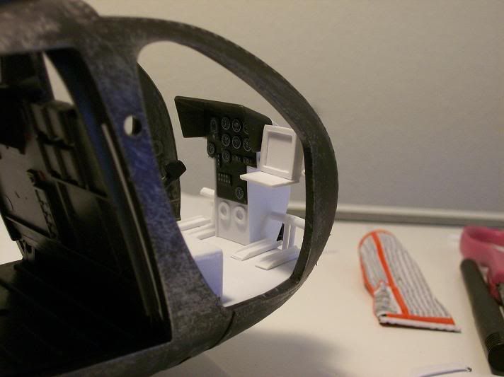
I figured I could reuse the instrument panel, because scratch-building the whole thing scared me. I used styrene sheet again to build it.
Now boys and girls, 500 series helicopters have been produced since the sixties, with a ridiculous number of models, configurations, and options, but I don't think there was ever an instrument pedestal produced that looked just like mine. At this point I'll make the disclaimer that all of the stuff I'm doing to this helicopter will be CLOSE to reality, but definitely not EXACT. Maybe I could, but I don't think my patience would allow me to.
Next was the foot pedals.
In the pic you can also see I built the seat bases and closed up an annoying gap between the front bulkhead and the frame on both sides. There are a lot gaps in this thing, actually. I had to clamp and glue the front floor down before adding the styrene because it was flexed upwards so much. In the pic you can also see I cut the two openings in the bulkhead behind the crew's heads. This was lots of fun and I only cut myself twice. The little "L" shaped bits on the front of the seat bases are where the cyclics are actually supposed to be mounted.
Most police helicopters nowadays are equipped with all sorts of electronic goodies, including a monitor and keyboard for the right hand seat. So, I needed a monitor and keyboard:
I mounted the pedestal and ran a piece of styrene tubing from there to the wall, and mounted the monitor on that. There are a bunch of different mounting methods I've seen on real helicopters, but this one was the easiest.
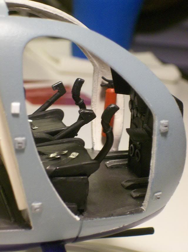
In the first pic you can see the modified rotor assm. again. I added a bit of the linkages that protrude upwards in front of the assm. It ain't all that accurate, but reproducing the real thing would have taken me about a month. I will later add a cable cutter right in front of the rotor assm.
The rear of the cockpit got some attention too. Gaps everywhere. The only thing I could do was close it all in with styrene sheet.
Next, the skids. Like I mentioned earlier, the mounting points needed to be adjusted because the body mounting points were cut down. Luckily, this involved removing material and not adding it. Always easier to remove. The fairings at the top of the skid legs were a bit too bulky and were cut down, as well as the bottom attachment points where skid and leg meet, although I hadn't yet done it all when I took the picture.
I also added the foot pegs with styrene rod.
Tail rotor next. Way too bulky and simplified. I shaved some bits down and added the largest and most obvious parts of the linkage. I thought about adding a twin cascading rotor assm. but decided against it. I'll likely do more work to this part but I'll need some smaller styrene rod.
That's all I got for now. I'll likely do the seats next, so stay tuned!
Jeffrey