I vote to leave the antenna on and make the ammo can smaller.
For those of you wanting to cut out the crew chief door. I just did one of mine. It came out pretty clean but there is some work to be done to make it look right as the bulkhead is not flush behind the door with the hull. Also, the door probably needs to be cut in half as if you slide it all the way to open it is still too large. The real ones have two smaller doors that overlap each other so when fully open it appears as one smaller door. Some type of styrene strip also needs to be added to the bottom to "receive" the bottom of the door and act as a guide.
I also removed the ordnance armlet and found a screw sticking out of the hull. At that point I decided to take the whole thing apart but ended up stripping 2 screws and couldn't get the thing apart to take out the screw left from removing the "armlet."
If I put the armlet back on it is way too big and covers a large portion of the crewchief window. The real ones have a smaller scale armlet. Anyway, the plug PH is making will work if you want to leave the crewchief door closed, but if you were planning on opening it up, the armlet covers way too much of the door opening.
This is turning into more work than I anticipated so may just go with the crewchief doors closed and external mounted miniguns.
Will post some pics if I have time later.
Phil
1/18 Pavehawk Custom Mods
-
pcoughran
- Officer - 1st Lieutenant

- Posts: 596
- Joined: Mon Jun 30, 2008 10:58 am
- Location: 1, USA, MO, St. Louis
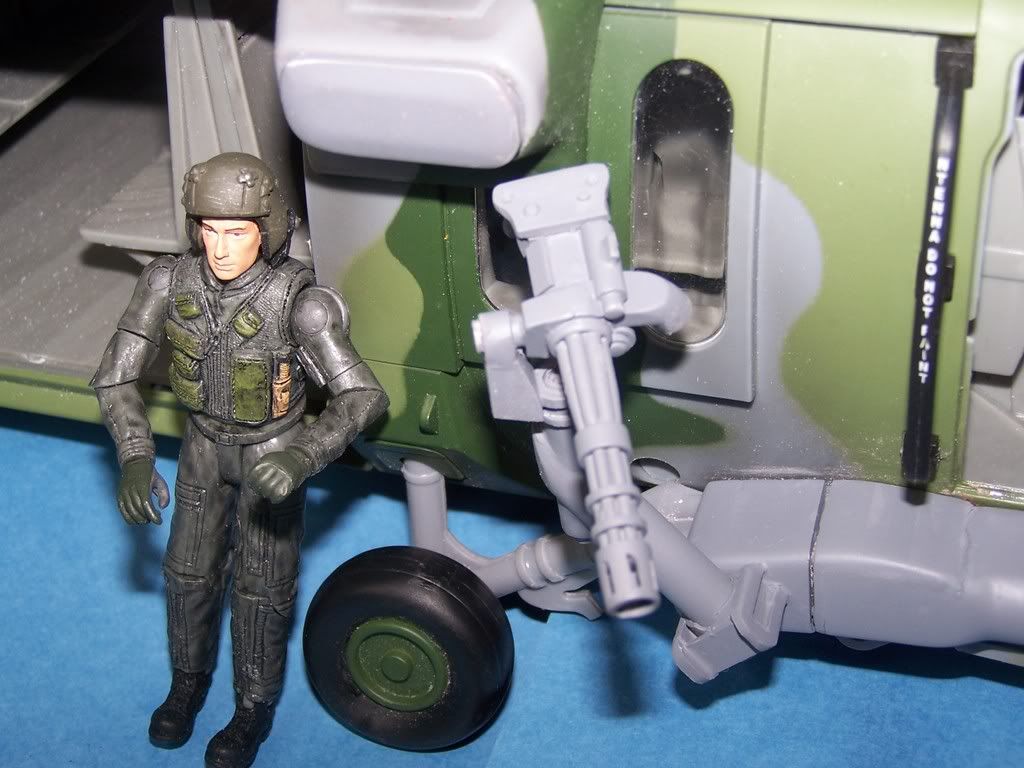
Pics to better explain last post above.
The first and second show the ugly screw left when the armlet is removed.


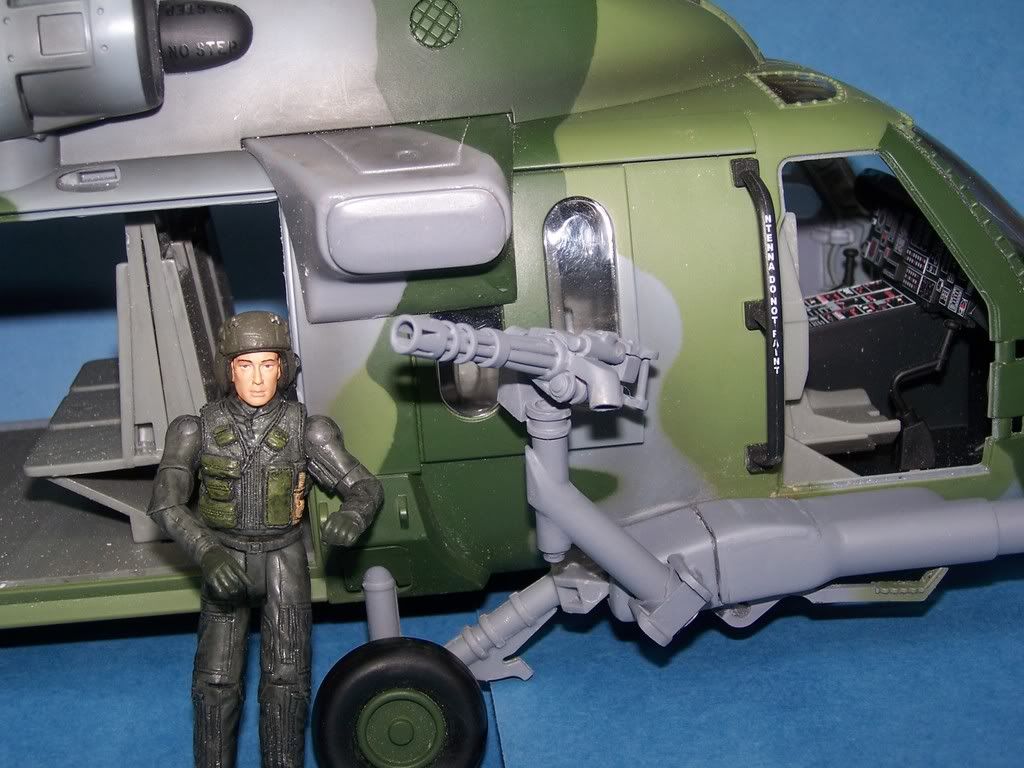
The second also shows the door is obviously too large and needs to be cut in half. Only one of the real two sliding doors is visible when opened all the way as one slides over the other.

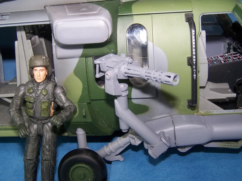
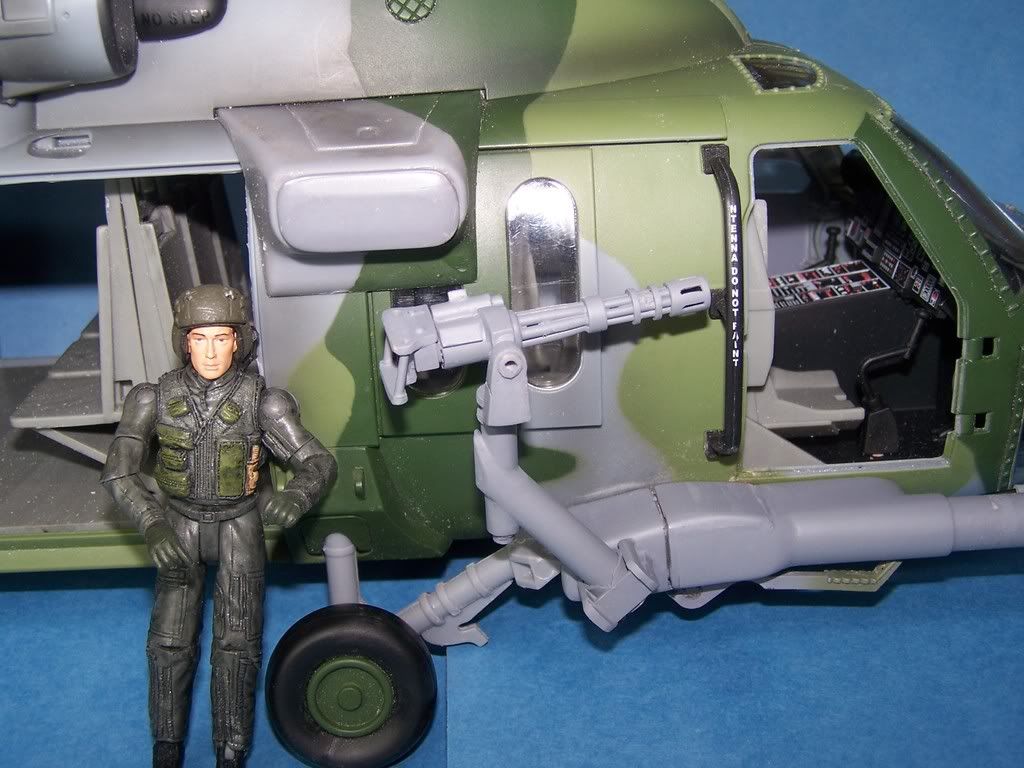
Notice in this 3rd picture above how much smaller the armlet is and how little of the window is blocked.

Even if the window is cut in half and full opening is there, the BBI armlet is too large, I feel to make the internal gun mounts work well.
The ugly screw is coming from inside the hull. Like I said before, I stripped 2 screws accidentally trying to get the hull apart to I could take the bulkhead out to get to the screw. If I could get that screw out or rid of it I would just do without the armlet completely and fill the gaps left by the screw and the small strip of the armlet on top of the fuselage. Any ideas?
Phil
The first and second show the ugly screw left when the armlet is removed.
The second also shows the door is obviously too large and needs to be cut in half. Only one of the real two sliding doors is visible when opened all the way as one slides over the other.
Notice in this 3rd picture above how much smaller the armlet is and how little of the window is blocked.
Even if the window is cut in half and full opening is there, the BBI armlet is too large, I feel to make the internal gun mounts work well.
The ugly screw is coming from inside the hull. Like I said before, I stripped 2 screws accidentally trying to get the hull apart to I could take the bulkhead out to get to the screw. If I could get that screw out or rid of it I would just do without the armlet completely and fill the gaps left by the screw and the small strip of the armlet on top of the fuselage. Any ideas?
Phil
"Where's dat waskily wabbit?"
____________________________________________
Good Trades: Ostketten, Pickelhaube, Cornbreadfred, Sledgehammer, Pizzaguy, caesarbc3,jwcarpenter
____________________________________________
Good Trades: Ostketten, Pickelhaube, Cornbreadfred, Sledgehammer, Pizzaguy, caesarbc3,jwcarpenter
-
pickelhaube
- Officer - Brigadier General

- Posts: 9647
- Joined: Mon Jan 22, 2007 5:52 am
- Location: New Orleans
The second also shows the door is obviously too large and needs to be cut in half. Only one of the real two sliding doors is visible when opened all the way as one slides over the other.
Notice in this 3rd picture above how much smaller the armlet is and how little of the window is blocked.
Even if the window is cut in half and full opening is there, the BBI armlet is too large, I feel to make the internal gun mounts work well.
The ugly screw is coming from inside the hull. Like I said before, I stripped 2 screws accidentally trying to get the hull apart to I could take the bulkhead out to get to the screw. If I could get that screw out or rid of it I would just do without the armlet completely and fill the gaps left by the screw and the small strip of the armlet on top of the fuselage. Any ideas?
Phil[/quote]
Hey Phil,
It looks to me that if you cut the middel out of the stub and glue them back together and do a little shaping on the bottom wear it overhangs the window will get you were you have to go.
In the photos I have seen some of the Paves have the stub plug with nav light and others are totally devoid of it altogether.
I would say cut about 1/2 inch to 3/4 out of the middel and that way you can hide the screw tap.
Kirk Douglas : Mine hit the ground first
John Wayne : Mine was taller

John Wayne : Mine was taller
-
pickelhaube
- Officer - Brigadier General
- Posts: 9647
- Joined: Mon Jan 22, 2007 5:52 am
- Location: New Orleans
Ok,
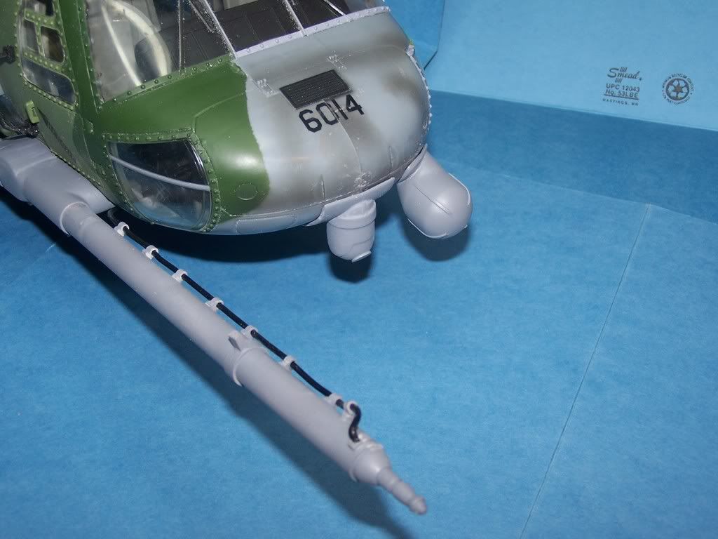
What I am going to do is cut the tube right off at the center ring sand down the stubs and cast the whole front and tip up to the ring. I think that this will be a good compromise. You will get some detail at the business end.
The hydrolic line WILL NOT BE CAST THE LITTLE SUBS ONLY

What I am going to do is cut the tube right off at the center ring sand down the stubs and cast the whole front and tip up to the ring. I think that this will be a good compromise. You will get some detail at the business end.
The hydrolic line WILL NOT BE CAST THE LITTLE SUBS ONLY
Last edited by pickelhaube on Mon Apr 06, 2009 10:24 am, edited 1 time in total.
Kirk Douglas : Mine hit the ground first
John Wayne : Mine was taller
John Wayne : Mine was taller

G’day Spikeman
Looks to me the main issue with the wing strut mounting points is that BBI mounted them too far forward, in the pictures it is clearly centred on the pillar between the main cabin door and the crew chiefs window, however BBI chose to mount them centred on the outer edge of the pillar.
Here’s a quick and dirty photoshop to show the potential difference of moving the strut mounts backwards would have.

Moving it back a little and rounding off or trimming the lower portions of the strut mounting points should make it over all a little more acceptable.
I’ve looked at the strut sockets of mine several times and realised that there must be some securing them but could not see what, so how do you access the retaining screw for the them anyway?
Looks to me the main issue with the wing strut mounting points is that BBI mounted them too far forward, in the pictures it is clearly centred on the pillar between the main cabin door and the crew chiefs window, however BBI chose to mount them centred on the outer edge of the pillar.
Here’s a quick and dirty photoshop to show the potential difference of moving the strut mounts backwards would have.
Moving it back a little and rounding off or trimming the lower portions of the strut mounting points should make it over all a little more acceptable.
I’ve looked at the strut sockets of mine several times and realised that there must be some securing them but could not see what, so how do you access the retaining screw for the them anyway?
Last edited by Spudkopf on Sat Jan 31, 2009 7:47 pm, edited 1 time in total.
SPUD
Something's up with photobucket?????

Something's up with photobucket?????
-
pcoughran
- Officer - 1st Lieutenant
- Posts: 596
- Joined: Mon Jun 30, 2008 10:58 am
- Location: 1, USA, MO, St. Louis
Spud,
You may be onto something. I have to decide how much more "cutting up" I'm willing to do but it may be a pretty easy fix to just move the ordnance arm back. It's still too big (scale is wrong) but it definitely wouldn't be as noticeable if slid back some and it would still hide the screw.
I didn't realize it was screwed down till I popped it off. If you look inside the cabin at the top where the piece slides through that slot at the top you will see that it has a little notch that secures it when it is slid in (you kind of have to put the notch end in first at an angle then rotate and push to snap it in. I did the exact opposite to get it off. I used a screwdriver and put it in the slot on the front of the ordnance arm (not the one on top of the cabin/fuselage) then I used it as a lever applying pressure pushing the screwdriver back towards the rear of the aircraft which pulls the front edge of the ordnance arm out and away. The screw came out of the ordnance arm fairly easy - no popping noise or anything - I didn't even know it was screwed till it came all the way off and I saw the screw sticking out. I'm guessing to remove the screw you'd have to separate the hull by unscrewing several screws which are behind screw plugs. I removed all but two which I guess are stripped cause I couldn't get them out. After separating the hull I'm guessing the cabin bulkhead is a separate piece inside and it is hiding the screw that holds the ordnance arm (you can't see it when you look inside the cabin).
It appears to me that the hull is not only screwed together but glued as well? So, separating it should be approached with patience. Since I won't be getting mine apart any farther I'll try to work around the screw.
If this was confusing I could post a picture showing how I got the ordnance arm off. let me know if you need it.
Phil
"Where's dat waskily wabbit?"
____________________________________________
Good Trades: Ostketten, Pickelhaube, Cornbreadfred, Sledgehammer, Pizzaguy, caesarbc3,jwcarpenter
____________________________________________
Good Trades: Ostketten, Pickelhaube, Cornbreadfred, Sledgehammer, Pizzaguy, caesarbc3,jwcarpenter
-
pickelhaube
- Officer - Brigadier General
- Posts: 9647
- Joined: Mon Jan 22, 2007 5:52 am
- Location: New Orleans
I am not sure about Spud but you lost me.pcoughran wrote:Spud,
You may be onto something. I have to decide how much more "cutting up" I'm willing to do but it may be a pretty easy fix to just move the ordnance arm back. It's still too big (scale is wrong) but it definitely wouldn't be as noticeable if slid back some and it would still hide the screw.
I didn't realize it was screwed down till I popped it off. If you look inside the cabin at the top where the piece slides through that slot at the top you will see that it has a little notch that secures it when it is slid in (you kind of have to put the notch end in first at an angle then rotate and push to snap it in. I did the exact opposite to get it off. I used a screwdriver and put it in the slot on the front of the ordnance arm (not the one on top of the cabin/fuselage) then I used it as a lever applying pressure pushing the screwdriver back towards the rear of the aircraft which pulls the front edge of the ordnance arm out and away. The screw came out of the ordnance arm fairly easy - no popping noise or anything - I didn't even know it was screwed till it came all the way off and I saw the screw sticking out. I'm guessing to remove the screw you'd have to separate the hull by unscrewing several screws which are behind screw plugs. I removed all but two which I guess are stripped cause I couldn't get them out. After separating the hull I'm guessing the cabin bulkhead is a separate piece inside and it is hiding the screw that holds the ordnance arm (you can't see it when you look inside the cabin).
It appears to me that the hull is not only screwed together but glued as well? So, separating it should be approached with patience. Since I won't be getting mine apart any farther I'll try to work around the screw.
If this was confusing I could post a picture showing how I got the ordnance arm off. let me know if you need it.
Phil
Kirk Douglas : Mine hit the ground first
John Wayne : Mine was taller
John Wayne : Mine was taller

-
pcoughran
- Officer - 1st Lieutenant
- Posts: 596
- Joined: Mon Jun 30, 2008 10:58 am
- Location: 1, USA, MO, St. Louis
Spud,
Looking forward to the Aussie Open with Federer vs. Nadal tomorrow. Is tennis pretty big down under?
Anyway, here's a few pics hope they help.
As far as the ordnance arm goes this is looking thru the port side cabin to the inside of the opposite side where you can see the inside connection and where the screw to mount the ordnance arm is hidden behind the bulkhead.

To get the arm off I used the handle of my exacto knife (blade covered of course) but this picture shows a screwdriver

push the handle back towards the tail rotating the arm clockwise out by applying a decent amount of pressure.

Here's the arm out and you can see how it is notched on one side

A picture of the backside of the ordnance arm

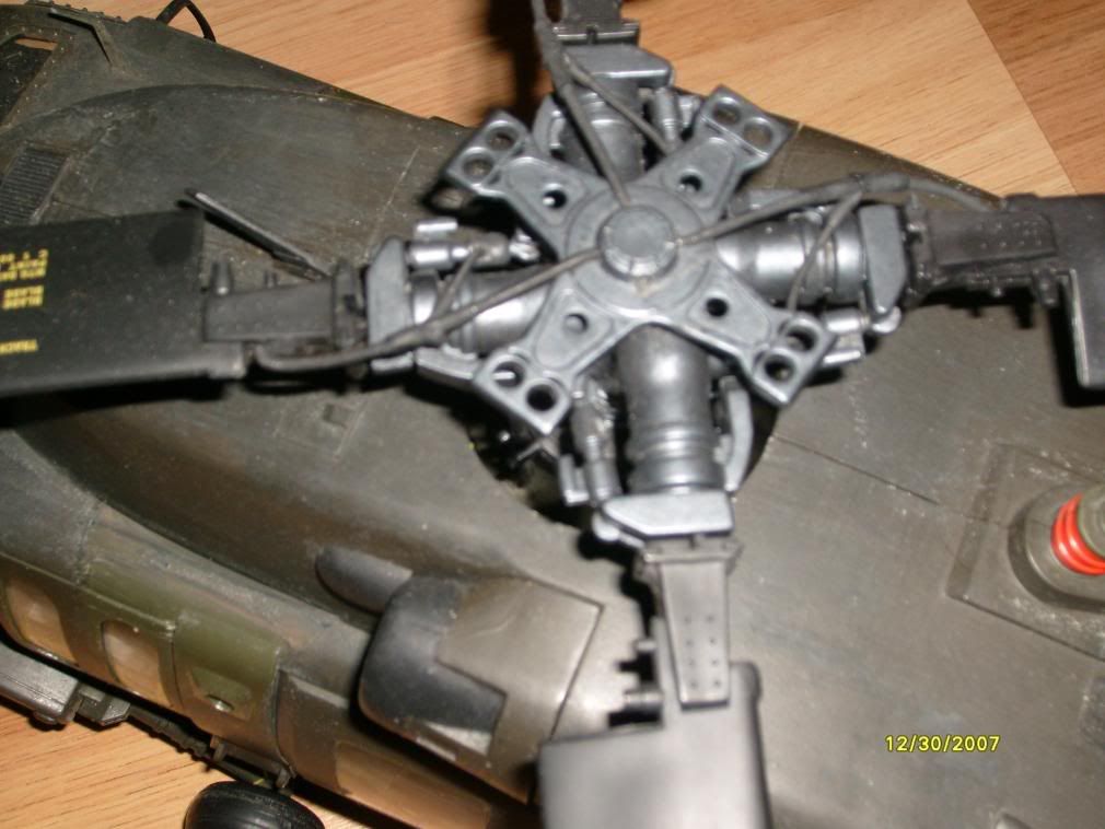
Finally, a picture showing the location of all the screws that hold the hull together. They are behind plugs. I just predrilled a small hole in the center of the plug then put a drywall screw in and jiggled till the plug came out then you have access to the screws. They are set pretty deep inside and have a pretty small head so make sure you have the right size screwdriver or you may strip some like I did.

Phil
Looking forward to the Aussie Open with Federer vs. Nadal tomorrow. Is tennis pretty big down under?
Anyway, here's a few pics hope they help.
As far as the ordnance arm goes this is looking thru the port side cabin to the inside of the opposite side where you can see the inside connection and where the screw to mount the ordnance arm is hidden behind the bulkhead.
To get the arm off I used the handle of my exacto knife (blade covered of course) but this picture shows a screwdriver
push the handle back towards the tail rotating the arm clockwise out by applying a decent amount of pressure.
Here's the arm out and you can see how it is notched on one side
A picture of the backside of the ordnance arm
Finally, a picture showing the location of all the screws that hold the hull together. They are behind plugs. I just predrilled a small hole in the center of the plug then put a drywall screw in and jiggled till the plug came out then you have access to the screws. They are set pretty deep inside and have a pretty small head so make sure you have the right size screwdriver or you may strip some like I did.
Phil
"Where's dat waskily wabbit?"
____________________________________________
Good Trades: Ostketten, Pickelhaube, Cornbreadfred, Sledgehammer, Pizzaguy, caesarbc3,jwcarpenter
____________________________________________
Good Trades: Ostketten, Pickelhaube, Cornbreadfred, Sledgehammer, Pizzaguy, caesarbc3,jwcarpenter
Thanks again Phil, the pic's make it quite clear (even Mat' should be able to understand it ).
Tennis, don't get me started, my wife has been umpiring the open (as a lines person) and also the Kooyong Classic the week before, when she's not actually at the open it's on the TV in fact I've been told that the plasma's booked for the evening and if I want to watch TV I'll be relegated to use the barely functional tiny screened CRT, bummer think I’ll just read a war book instead (Apache Dawn is what I’m currently reading, it’s about an UK army Apache Afghanistan deployment in summer of 2007 and just finished reading Roberts Ridge which I can highly recommend).
My daughter is talking about taking up umpiring this years as well, my nephew is also at the open as one of the ball kiddies and my son looks to be applying for this next year.
For me personally, my once a week hit and giggle night social tennis is already too much, but the rest of the family can't seem to get enough of the silly stuff.
SPUD
Something's up with photobucket?????
Something's up with photobucket?????
-
USCGSARdog
- Officer - 1st Lieutenant
- Posts: 619
- Joined: Mon Oct 04, 2004 6:42 pm
- Location: Richmond, VA
I have disassembled two of my Blackhawks for conversion projects and yes, the fuselages are screwed AND glued together. The best way I have found to separate the two halves is to first remove all of the screw hole plugs. Then, using a large phillips precision screw driver, remove all of the screws shown in the post above. Once the screws are removed, use a large ex-acto to cut and gently pry at the glued joints. Keep in mind, there are press fit sockets in the nose area to hold the fuse together, along with a pretty funky seam line. I usually work from the rear of the cabin forward to make the job a little easier once I reach once I reach this area. Also, the windshield and cockpit overhead windows are glued to the fuse after it is assembled, therefore holding the fuse halves together as well. The glue used is very flexible, so just gently pry and cut the windows free. The windshield also has a few mounting tabs that you should try and preserve for for reassembly of the fuselage. Once the halves are separated, you will find an "H" shaped interior wall piece surrounding the crew windows. This is where the bulk of the work will need to be done in order to open up the crew windows and make it look good. This piece is glued to the fuselage wall along with press fit sockets. Be careful removing them, they are tuff. The only way to remove them is to gently pry them off.
Can this conversion be done reasonably? In my opinion, defiantly. Is it easy? It can be, if you take your time. The end result will be certainly be worth your effort.
Hey PH.... You are doing a hell of a job on these parts, they look great. I'm down for a full set when they are ready. I have a Blackhawk fully disassembled and ready to go.
Keep up the good work.
-Rob
_______________________________
"You have to go out, but you don't have to come back".
"You have to go out, but you don't have to come back".
-
pickelhaube
- Officer - Brigadier General
- Posts: 9647
- Joined: Mon Jan 22, 2007 5:52 am
- Location: New Orleans
Well not to much work on this this week. My regular work kicked in and it is like a shot in the arm as far as my finances are concerned. But I did get hold of one of my favorite songs with some helo action thrown in. What more can you ask for ?
http://www.youtube.com/watch?v=-f1cwycSWq0
http://www.youtube.com/watch?v=-f1cwycSWq0
Kirk Douglas : Mine hit the ground first
John Wayne : Mine was taller
John Wayne : Mine was taller
-
VMF115
- Officer - Brigadier General
- Posts: 7112
- Joined: Mon Jul 03, 2006 7:30 pm
- Location: Clear Lake, South Dakota
you also need to add the pitot tubes and other antenna
I would only be interested if those are added..
my biggest problem is what to do with the gunners doors...removing them without doing unreversable damaging is daunting you need a real steady hand to achieve this.......
but I want mydoor gunners doors to opean and close.
DAM you bbi!!!!!!!!!!! you should have not overlooked the small stuff........
Last edited by VMF115 on Wed Feb 04, 2009 7:09 pm, edited 1 time in total.
-
pickelhaube
- Officer - Brigadier General
- Posts: 9647
- Joined: Mon Jan 22, 2007 5:52 am
- Location: New Orleans
The antenna is on top. Does a helo even have a pitot tube ? I do not know were it is located. If you go with the exterior gun mounts NO CUTTING OF THE WINDOW WILL HAVE TO BE DONE.VMF115 wrote:you also need to add the pitot tubes and other antenna
I would only be interested if those are added..
my biggest problem is what to do with the gunners doors...removing them without doing unreversable damaging is daunting you need a real steady hand to achieve this.......
Kirk Douglas : Mine hit the ground first
John Wayne : Mine was taller
John Wayne : Mine was taller
-
VMF115
- Officer - Brigadier General
- Posts: 7112
- Joined: Mon Jul 03, 2006 7:30 pm
- Location: Clear Lake, South Dakota
they are on the top right above the pilot and copilot.pickelhaube wrote:The antenna is on top. Does a helo even have a pitot tube ? I do not know were it is located. If you go with the exterior gun mounts NO CUTTING OF THE WINDOW WILL HAVE TO BE DONE.VMF115 wrote:you also need to add the pitot tubes and other antenna
I would only be interested if those are added..
my biggest problem is what to do with the gunners doors...removing them without doing unreversable damaging is daunting you need a real steady hand to achieve this.......
-
pickelhaube
- Officer - Brigadier General
- Posts: 9647
- Joined: Mon Jan 22, 2007 5:52 am
- Location: New Orleans
Enough with the 1/18 scale Doomsday already. 1/18 scale will continue as long as we want it to.
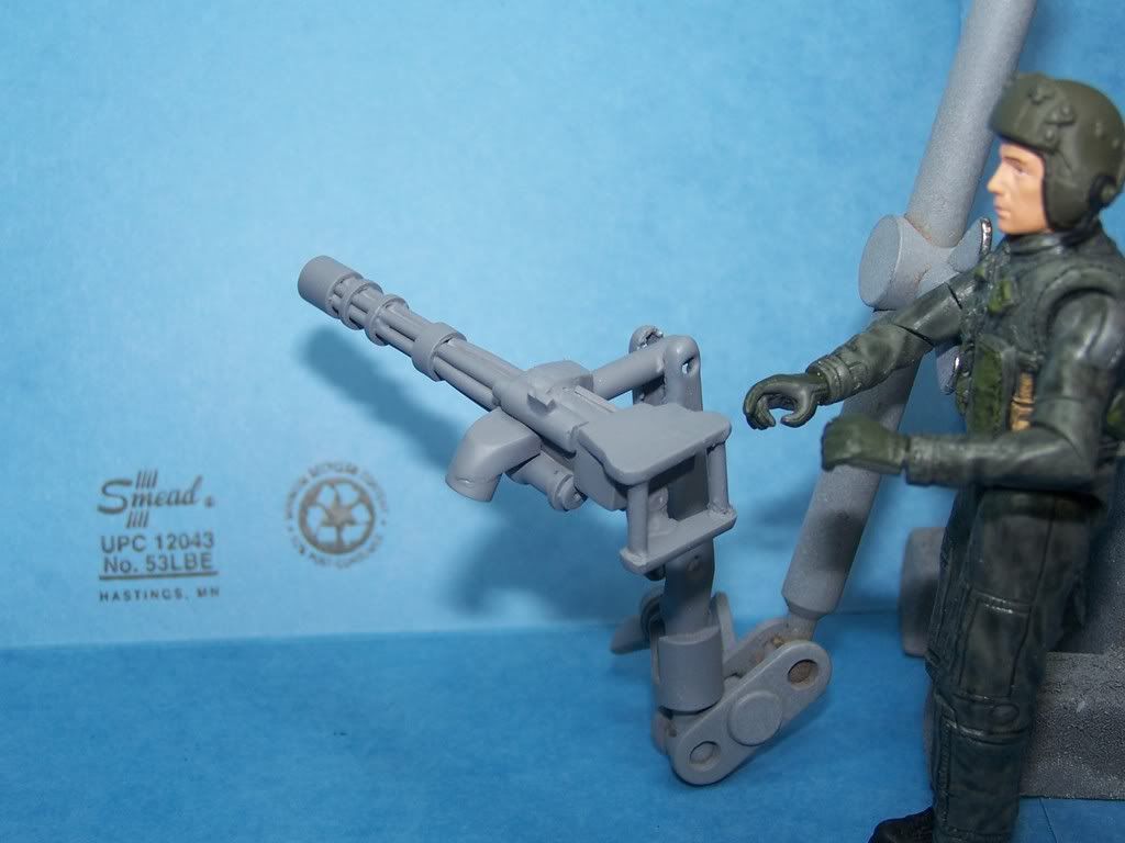
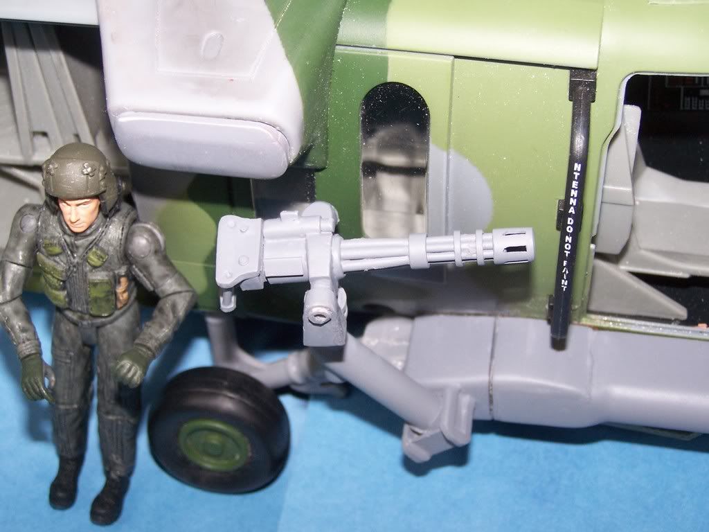
Moving on. I fiddeled around with the exterior mount today and it looks like that the hard point may have to be moved back like Phil Spud and Patrick said. The mini gun should be in about the center of the small double window. Inside mount outside mount it does not matter. If you do not move the hard point the base of it may be slam up next to the gun. If anything you will have to shave the base so it will not least LOOK tight next to it. I may have the starbord side mount made hopefully late Friday or for sure it will be done on Sat.
Calm down guys who is it that said " the reports of my death are a bit premature "
As long as we as collectors enjoy this hobby it will continue to live. Some of the helmets I have are over 120 years old. That hobby has been alive for that long.
I also have about a dozed stereo viewers that are over 100 years old. That hobby is alive and well since it was started by all of our great great Granmothers.
Kirk Douglas : Mine hit the ground first
John Wayne : Mine was taller
John Wayne : Mine was taller
-
pickelhaube
- Officer - Brigadier General
- Posts: 9647
- Joined: Mon Jan 22, 2007 5:52 am
- Location: New Orleans
-
pickelhaube
- Officer - Brigadier General
- Posts: 9647
- Joined: Mon Jan 22, 2007 5:52 am
- Location: New Orleans
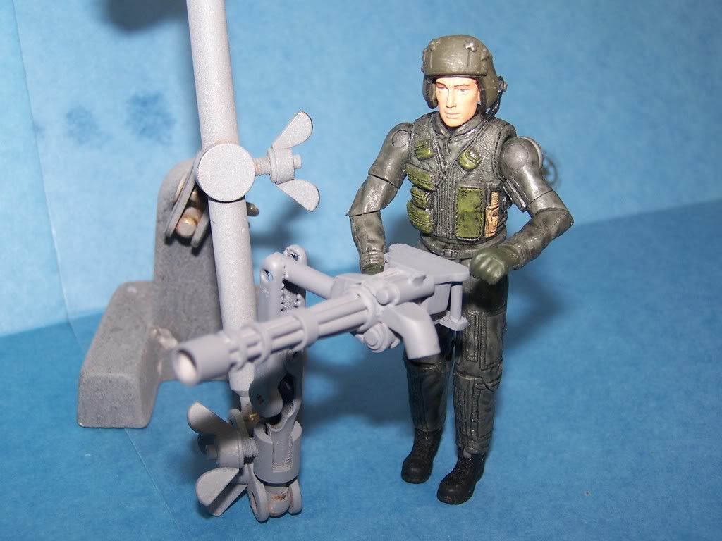
Well I cut the slots in the flash supresser ( what a pain ) and finished the starbard side gun mount . The slots need to be touched up but I was in a hurry to get some pics out.I am not sure how the slots will take in the molding process but I will try. Worst case senario is that the flash may be made without the slots. We will see.
All I have to do is make the port side wheel wrap around gun base and the amo boxes and this project is about done for the proto type making. I will see how the demand is to see if I make the internal gun mounts. The outside gun mounts may be the least used of the mounts but you do not have to cut the window.
I need to talk to Matt over at Fox Hole Toys but we are almost ready to take preorders. We are close on prices. That will be addressed a little later.
If I get a good day in tomorrow I will be done with the boxes.
Kirk Douglas : Mine hit the ground first
John Wayne : Mine was taller
John Wayne : Mine was taller
-
pickelhaube
- Officer - Brigadier General
- Posts: 9647
- Joined: Mon Jan 22, 2007 5:52 am
- Location: New Orleans
Everyone must be too busy clicking refresh at MD to even notice this. Those guns look great, better than I imagined. When you get the other side mounted, can you show us the pics. I don't know if I can afford the fuel probe and radomes, so I want to see how the mounts look without that attached. Anyways, amazing job, you exceed my expectations and I will be buying a set.